In this article, we will show you a UML Diagram Java Example. First of all, we will analyze what is UML of a class in java and what is the use of them. Last but not least we will talk about the types of diagrams and some examples.
1. Introduction
A UML diagram is a diagram based on the UML (Unified Modeling Language) that represent visually a program/code with its main actors, roles, actions, artifacts, or classes in ordering a person to understand better and maintain the information of the program/code. UML was created in the 1990s in order to resolve the chaos around software development and its documentation. In fact, it’s one of the most popular business process modeling techniques.
2. Technologies Used
To create the UML diagram examples in Java we used the free online program Draw.io.
3. Goals of UML
The most important goals of the UML diagrams in a class are:
- Provide users with a ready-to-use, expressive visual modeling language so they can develop meaningful models.
- Extensibility and specialization mechanisms to extend the core concepts.
- A formal basis for understanding the modeling language.
- Encourage the growth of the OO tools market.
- Be independent of particular programming languages and development processes.
- Support higher-level development concepts such as collaborations, frameworks, and patterns.
- Integrate best practices.
4. List of the UML components
Here we will analyze all the UML components in Java that are used to build a UML diagram in Java class. The building blocks of UML can be divided into three categories:
- Things
- Relationships
- Diagrams
4.1 Things
Every category have subcategories. Things consists of:
- Structural
- Behavioral
- Grouping
- Annotational
4.1.1 Structural things
Structural things are used to define the static part of the model and represent the elements. These elements are:
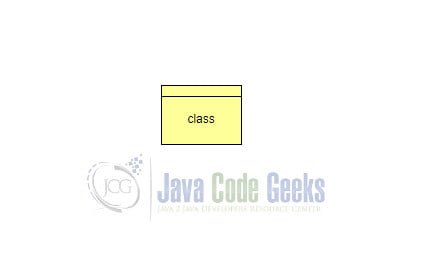
Class: Represents a set of objects.
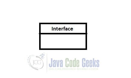
Interface: Defines a set of operations.
Collaboration: Defines the interaction between elements.
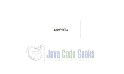
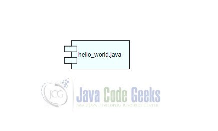
Component: Describes the physical part of a system.
Use case: Represents a set of actions performed by the program.
Node: A physical element that exists at run time.
4.1.2 Behavioral Things
Behavioral things are made up of the dynamic parts of UML models. There are:
Interaction: Interaction is a behavior that sends messages between the elements for a particular task.
State machine: It defines the sequence of states an object goes through in response to events.
4.1.3 Grouping Things
Grouping things are the mechanism that group elements of the UML model.
Package: This is the mechanism that can group the structural and behavioral things.
4.1.4 Annotational Things
Annotational things are a mechanism to capture remarks, descriptions, and comments of UML model components in a class.
Note :Is used to render comments, constraints and more of a UML model.
4.2 Relationship
The relationship is the most important block of the UML. Its purpose is to describe the connection between two elements and the functionality of an app. The relationships between the two elements are:
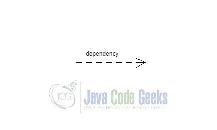
Dependency: When you change something on the first element then this change affects the other.
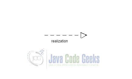
Realization: One element describes some responsibility that is not being met and the other implements it.
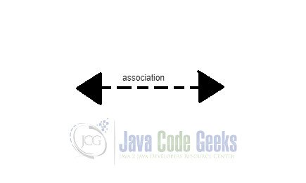
Association: It describes how many objects are taking part in a relationship.
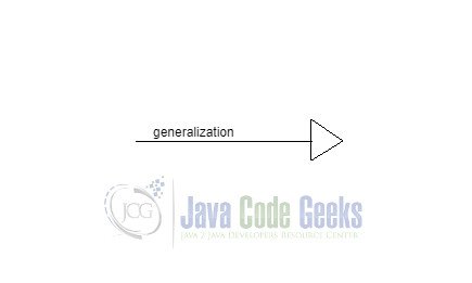
Generalization: Describe the inheritance relationship between a specialized element with a generalized element.
5. Types of Diagrams
Here we will analyze every UML diagram that we use in a class and the use of them. First of all, we must know that a UML model is not capable to cover every aspect of a program but it helps us to have a first look at its functions and data as well as its complexity. Let’s not forget that a picture is worth a thousand words but each person has their perspective to analyze it.
There are two categories of diagrams and these in turn have some subcategories. The two main categories are:
- Structural Diagrams
- Behavioral Diagrams
5.1 Structural Diagrams
The structural diagrams represent the main structure of the model and it is static. These parts are built by classes, objects, interfaces, and nodes. These diagrams are:
- Class diagram
- Component diagram
- Object diagram
- Deployment diagram
5.1.1 Class diagram
Class diagrams are the most famous diagrams and they are used mostly for development. Their purpose is to show the static object-oriented view of a program. An example is:
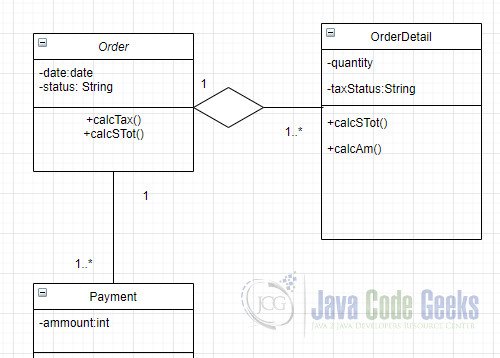
Every rectangle is a class. Inside them in the first half have the attributes and the second half have the functions of the class. The symbols ‘+’,’-‘ and ‘#’ are used to declare if the attribute is public or private or protected. Then we can see the connections between them in which the connection with rhomb is the aggregation which shows the dependence between the two classes. Last but not least there are the numbers on the relationships and declare the cardinality.
5.1.2 Component diagram
Component diagrams show a group of components such as classes or interfaces and the connections between them. Their purpose is to visualize the implementation. An example is:
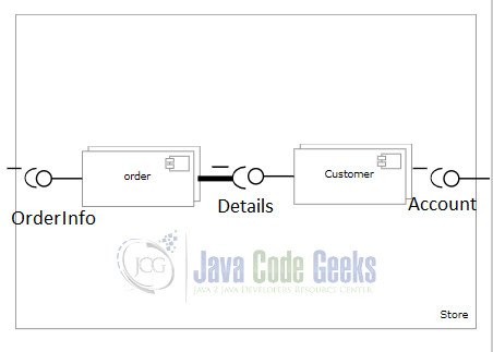
Here we can see two classes ‘Order‘ and ‘Customer‘ and the component interfaces such as ‘Details‘ that is used to connect the two classes.
5.1.3 Object Diagram
Objects diagrams have very commons with class diagrams such as they represent a static view and are created by the object. The difference between them and the reason that it exists is that they represent an instance of a class diagram for more practical purposes and real-life scenarios. An example is:
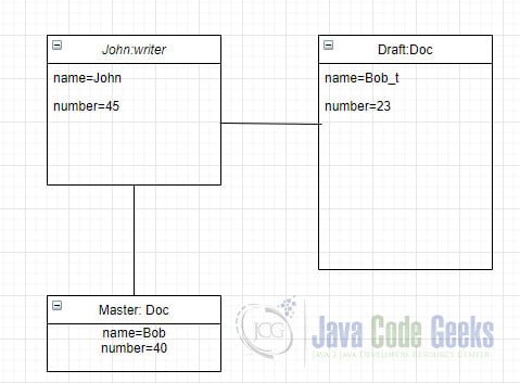
In this example, we can see that object diagram and a class diagram are very similar. We have 3 different instances of the classes with their attributes.
5.1.4 Deployment Diagram
Deployment diagrams are used to visualize the deployment view of a program. A deployment diagram can be created by nodes that are physical entities in which the components are deployed. An example is:
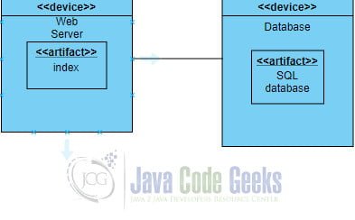
Here we can see the two nodes ‘Web server‘ and ‘Database‘ with their components ‘index’ and ‘SQL database’. These two nodes connect with an association.
5.2 Behavioral Diagrams
The behavioral diagrams’ purpose is to cover full of the static and dynamic aspects of a program. In other words, behavioral diagrams are used to describe the changing parts of the system.
5.2.1 Use case diagram
The use case diagrams are used to show a particular functionality of a program and to describe the connections between the functionalities and their controllers/actors. An example is:
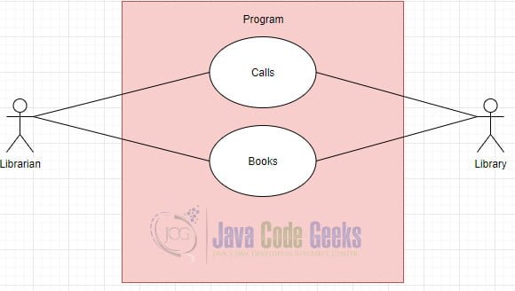
Here you can see a program that has two functions ‘Calls’ and ‘Books’ that have communication Links to two actors that can trigger these functions of the program.
5.2.2 Statechart diagram
The statechart is used to show the reaction of a program when it affects by factors. In other words, describe the change of the classes and interfaces. An example is:
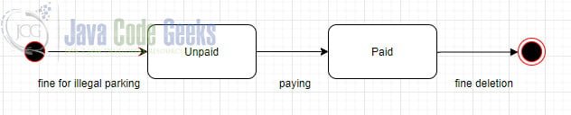
In this example, we can see a program for a fine for illegal parking. At first, we start with the Initial pseudo-state. Then we have two states ‘Unpaid‘ nad ‘Paid‘ that we must cross to finally end the program.
5.2.3 Sequence diagram
The sequence diagrams are used to show the organization of objects and the interaction between them. In particular, at sequence diagrams, we design the sequence of messages that one object sends to another. An example is:
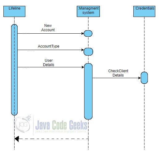
In this example, we can see a program that is used to create an account for a library. The 3 objects(Lifeline, Management system, Credentials)trough the messages(connections) and functions can check the details of the user for the new account.
5.2.4 Collaboration diagram
The collaboration diagram’s purpose is to show the organization of objects and their interaction. It is very similar to the sequence diagram. An example is:
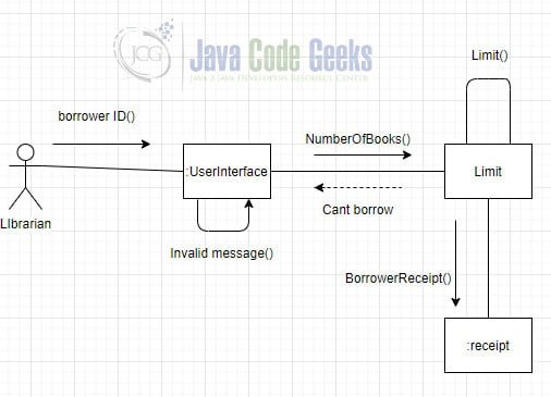
Here you can see an example in which a borrower tries to borrow some books from the library. First, we check the borrower ID and if the ID is not invalid we check if the number of books is bigger than the limit. Finally, we create a receipt.
5.2.5 Activity diagram
Activity diagrams are used to show the flow of controls in a program and to give to the developer a theoretical first look of its execution. Activities are the functions of the program. An example is:
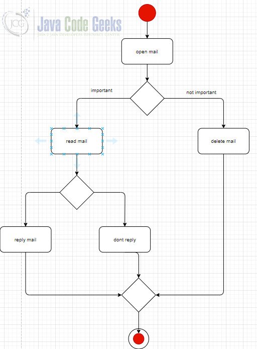
6. UML Diagram in Java
In this UML Diagram Java example, we can see the functionality of a class that opens mails and decide if the mail is important and we need to reply through some decision points(rhombus).

I would like to suggest to add a list of tools that support UML authoring and analysis. There is a number of general-purpose (eg https://www.lucidchart.com) but also more specialized ones (eg https://sourcespy.com) that allow for UML authoring and generation from the code.