This is a JavaFX Complex Shape Example. You can draw complex shapes using the Path class. An instance of the Path class defines the path (outline) of a shape. A path consists of one or more subpaths. A subpath consists of one or more path elements. Each subpath has a starting point and an ending point.
The following table shows an overview of the whole article:
Table Of Contents
The following examples use Java SE 7 and JavaFX 2.2.
1. The Path Class
1.1 The Code
FxComplexShapeExample1.java
import javafx.application.Application;
import javafx.scene.Scene;
import javafx.scene.layout.HBox;
import javafx.scene.shape.ClosePath;
import javafx.scene.shape.LineTo;
import javafx.scene.shape.MoveTo;
import javafx.scene.shape.Path;
import javafx.stage.Stage;

public class FxComplexShapeExample1 extends Application
{
	public static void main(String[] args)
	{
		Application.launch(args);
	}

	@Override
	public void start(final Stage stage)
	{
		// Create a Triangle
		Path triangle = new Path(new MoveTo(0, 0),
				new LineTo(0, 50),
				new LineTo(50, 50),
				new ClosePath());

		// Create a Star
		Path star = new Path();
				star.getElements().addAll(new MoveTo(30, 0),
				new LineTo(0, 30),
				new LineTo(60, 30),
				new ClosePath(),
				new MoveTo(0, 10),
				new LineTo(60, 10),
				new LineTo(30, 40),
				new ClosePath()

		// Create teh HBox
		HBox root = new HBox(triangle, star);
		root.setSpacing(10);

		// Set the Style of the HBox
		root.setStyle("-fx-padding: 10;" +
				"-fx-border-style: solid inside;" +
				"-fx-border-width: 2;" +
				"-fx-border-insets: 5;" +
				"-fx-border-radius: 5;" +
				"-fx-border-color: blue;");

		// Create the Scene
		Scene scene = new Scene(root);
		// Add the Scene to the Stage
		stage.setScene(scene);
		// Set the Title of the Stage
		stage.setTitle("A Path Example");
		// Display the Stage
		stage.show();
	}
}
A path element is an instance of the PathElement abstract class. The following subclasses of the PathElement class exist to represent specific type of path elements:
- MoveTo
- LineTo
- HLineTo
- VLineTo
- ArcTo
- QuadCurveTo
- CubicCurveTo
- ClosePath
The Path class contains three constructors:
- Path()
- Path(Collection elements)
- Path(PathElement… elements)
The no-args constructor creates an empty shape. The other two constructors take a list of path elements as arguments.
A Path stores path elements in an ObservableList<PathElement>. You can get the reference of the list using the getElements() method. You can modify the list of path elements to modify the shape.
1.2 The MoveTo Path Element
A MoveTo path element is used to make the specified x and y coordinates as the current point. It has the effect of lifting and placing the pencil at the specified point on the paper.
The first path element of a Path object must be a MoveTo element and it must not use relative coordinates. The MoveTo class defines two double properties that are the x and y coordinates of the point.
- x
- y
The MoveTo class contains two constructors. The no-args constructor sets the current point to (0.0, 0.0). The other constructor takes the x and y coordinates of the current point as arguments.
// Create a MoveTo path element to move the current point to (0.0, 0.0)
MoveTo mt1 = new MoveTo();
// Create a MoveTo path element to move the current point to (10.0, 10.0)
MoveTo mt2 = new MoveTo(10.0, 10.0);
1.3 The LineTo Path Element
A LineTo path element draws a straight line from the current point to the specified point. It contains two double properties that are the x and y coordinates of the end of the line:
- x
- y
The LineTo class contains two constructors. The no-args constructor sets the end of the line to (0.0, 0.0). The other constructor takes the x and y coordinates of the end of the line as arguments.
// Create a LineTo path element with its end at (0.0, 0.0)
LineTo lt1 = new LineTo();
// Create a LineTo path element with its end at (10.0, 10.0)
LineTo lt2 = new LineTo(10.0, 10.0);
With the knowledge of the MoveTo and LineTo path elements, you can construct shapes that are made of lines only.
The following snippet of code creates a triangle:
Path triangle = new Path(new MoveTo(0, 0),
new LineTo(0, 50),
new LineTo(50, 50),
new LineTo(0, 0));
1.4 The ClosePath Path Element
The ClosePath path element closes the current subpath. Note that a Path may consist of multiple subpaths, and, therefore, it is possible to have multiple ClosePath elements in a Path. A ClosePath element draws a straight line from the current point to the initial point of the current subpath and ends the subpath.
A ClosePath element may be followed by a MoveTo element, and in that case, the MoveTo element is the starting point of the next subpath.
If a ClosePath element is followed by a path element other than a MoveTo element, the next subpath starts at the starting point of the subpath that was closed by the ClosePath element.
You can rewrite the path for the previous triangle example using a ClosePath.
Path triangle = new Path(new MoveTo(0, 0),
new LineTo(0, 50),
new LineTo(50, 50),
new ClosePath());
1.5 The GUI
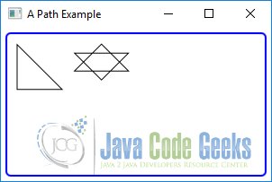
The following image shows the result of the above program. One triangle and one with two inverted triangles to give it a look of a star:
2. Using other Path Elements
2.1 The Code
FxComplexShapeExample2.java
import javafx.application.Application;
import javafx.scene.Scene;
import javafx.scene.control.CheckBox;
import javafx.scene.control.Label;
import javafx.scene.control.Slider;
import javafx.scene.layout.BorderPane;
import javafx.scene.layout.GridPane;
import javafx.scene.shape.ArcTo;
import javafx.scene.shape.HLineTo;
import javafx.scene.shape.MoveTo;
import javafx.scene.shape.Path;
import javafx.scene.shape.VLineTo;
import javafx.stage.Stage;

public class FxComplexShapeExample2 extends Application
{
	private ArcTo arcTo;

	public static void main(String[] args)
	{
		Application.launch(args);
	}

	@Override
	public void start(final Stage stage)
	{
		// Create the ArcTo path element
		arcTo = new ArcTo();

		// Use the arcTo element to build a Path
		Path path = new Path(new MoveTo(0, 0),
			new VLineTo(100),
			new HLineTo(100),
			new VLineTo(50),
			arcTo);

		// Create the BorderPane
		BorderPane root = new BorderPane();
		root.setTop(this.getTopPane());
		root.setCenter(path);

		// Set the Style of the BorderPane
		root.setStyle("-fx-padding: 10;" +
			"-fx-border-style: solid inside;" +
			"-fx-border-width: 2;" +
			"-fx-border-insets: 5;" +
			"-fx-border-radius: 5;" +
			"-fx-border-color: blue;");

		// Create the Scene
		Scene scene = new Scene(root);
		// Add the Scene to the Stage
		stage.setScene(scene);
		// Set the Title of the Stage
		stage.setTitle("An ArcTo Path Example");
		// Display the Stage
		stage.show();
	}

	// Create the GridPane
	private GridPane getTopPane()
	{
		// Create the CheckBoxes
		CheckBox largeArcFlagCbx = new CheckBox("largeArcFlag");
		CheckBox sweepFlagCbx = new CheckBox("sweepFlag");

		// CReate the Sliders
		Slider xRotationSlider = new Slider(0, 360, 0);
		xRotationSlider.setPrefWidth(300);
		xRotationSlider.setBlockIncrement(30);
		xRotationSlider.setShowTickMarks(true);
		xRotationSlider.setShowTickLabels(true);

		Slider radiusXSlider = new Slider(100, 300, 100);
		radiusXSlider.setBlockIncrement(10);
		radiusXSlider.setShowTickMarks(true);
		radiusXSlider.setShowTickLabels(true);

		Slider radiusYSlider = new Slider(100, 300, 100);
		radiusYSlider.setBlockIncrement(10);
		radiusYSlider.setShowTickMarks(true);
		radiusYSlider.setShowTickLabels(true);

		// Bind ArcTo properties to the control data
		arcTo.largeArcFlagProperty().bind(largeArcFlagCbx.selectedProperty());
		arcTo.sweepFlagProperty().bind(sweepFlagCbx.selectedProperty());
		arcTo.XAxisRotationProperty().bind(xRotationSlider.valueProperty());
		arcTo.radiusXProperty().bind(radiusXSlider.valueProperty());
		arcTo.radiusYProperty().bind(radiusYSlider.valueProperty());

		// Create the GridPane
		GridPane pane = new GridPane();
		pane.setHgap(5);
		pane.setVgap(10);
		pane.addRow(0, largeArcFlagCbx, sweepFlagCbx);
		pane.addRow(1, new Label("XAxisRotation"), xRotationSlider);
		pane.addRow(2, new Label("radiusX"), radiusXSlider);
		pane.addRow(3, new Label("radiusY"), radiusYSlider);

		return pane;
	}
}
2.2 The HLineTo Path Element
The HLineTo path element draws a horizontal line from the current point to the specified x coordinate. The y coordinate of the ending point of the line is the same as the y coordinate of the current point. The x property of the HLineTo class specifies the x coordinate of the ending point.
// Create an horizontal line from the current point (x, y) to (50, y)
HLineTo hlt = new HLineTo(50);
2.3 The VLineTo Path Element
The VLineTo path element draws a vertical line from the current point to the specified y coordinate. The x coordinate of the ending point of the line is the same as the x coordinate of the current point. The y property of the VLineTo class specifies the y coordinate of the ending point.
// Create a vertical line from the current point (x, y) to (x, 50)
VLineTo vlt = new VLineTo(50);
The following snippet of code creates the same triangle as discussed in the previous section. This time, you use HLineTo and VLineTo path elements to draw the base and height sides of the triangle instead of the LineTo path elements.
Path triangle = new Path(new MoveTo(0, 0),
new VLineTo(50),
new HLineTo(50),
new ClosePath());
2.4 The ArcTo Path Element
An ArcTo path element defines a segment of ellipse connecting the current point and the specified point.
It contains the following properties:
- radiusX
- radiusY
- x
- y
- XAxisRotation
- largeArcFlag
- sweepFlag
The radiusX and radiusY properties specify the horizontal and vertical radii of the ellipse.
The x and y properties specify the x and y coordinates of the ending point of the arc. Note that the starting point of the arc is the current point of the path.
The XAxisRotation property specifies the rotation of the x-axis of the ellipse in degrees. Note that the rotation is for the x-axis of the ellipse from which the arc is obtained, not the x-axis of the coordinate system of the node. A positive value rotates the x-axis counterclockwise.
The largeArcFlag and sweepFlag properties are Boolean type, and by default, they are set to false.
The following code snippet creates a path with an ArcTo path element:
// Create the ArcTo path element
arcTo = new ArcTo();

// Use the arcTo element to build a Path
Path path = new Path(new MoveTo(0, 0),
	new VLineTo(100),
	new HLineTo(100),
	new VLineTo(50),
	arcTo);
2.5 The GUI
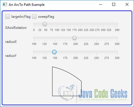
The above program uses an ArcTo path element to build a Path object. The program lets the user change properties of the ArcTo path element:
3. The PathElement Class
3.1 The Code
FxComplexShapeExample3.java
import javafx.application.Application;
import javafx.scene.Scene;
import javafx.scene.layout.HBox;
import javafx.scene.paint.Color;
import javafx.scene.shape.FillRule;
import javafx.scene.shape.LineTo;
import javafx.scene.shape.MoveTo;
import javafx.scene.shape.Path;
import javafx.scene.shape.PathElement;
import javafx.stage.Stage;

public class FxComplexShapeExample3 extends Application
{
	public static void main(String[] args)
	{
		Application.launch(args);
	}

	@Override
	public void start(final Stage stage)
	{
		// Create the PathElements

		// Both triangles use a counterclockwise stroke
		PathElement[] pathEleemnts1 = {new MoveTo(50, 0),
			new LineTo(0, 50),
			new LineTo(100, 50),
			new LineTo(50, 0),
			new MoveTo(90, 15),
			new LineTo(40, 65),
			new LineTo(140, 65),
			new LineTo(90, 15)};

		// One Triangle uses a clockwise stroke and
		// another uses a counterclockwise stroke
		PathElement[] pathEleemnts2 = {new MoveTo(50, 0),
			new LineTo(0, 50),
			new LineTo(100, 50),
			new LineTo(50, 0),
			new MoveTo(90, 15),
			new LineTo(140, 65),
			new LineTo(40, 65),
			new LineTo(90, 15)};

		// Create the Path

		// Using the NON-ZERO fill rule by default
		Path path1 = new Path(pathEleemnts1);
		path1.setFill(Color.LIGHTGRAY);

		Path path2 = new Path(pathEleemnts2);
		path2.setFill(Color.LIGHTGRAY);

		// Using the EVEN_ODD fill rule
		Path path3 = new Path(pathEleemnts1);
		path3.setFill(Color.LIGHTGRAY);
		path3.setFillRule(FillRule.EVEN_ODD);

		Path path4 = new Path(pathEleemnts2);
		path4.setFill(Color.LIGHTGRAY);
		path4.setFillRule(FillRule.EVEN_ODD);

		// Create the HBox
		HBox root = new HBox(path1, path2, path3, path4);
		root.setSpacing(10);

		// Set the Style of the HBox
		root.setStyle("-fx-padding: 10;" +
			"-fx-border-style: solid inside;" +
			"-fx-border-width: 2;" +
			"-fx-border-insets: 5;" +
			"-fx-border-radius: 5;" +
			"-fx-border-color: blue;");

		// Create the Scene
		Scene scene = new Scene(root);
		// Add the Scene to the Stage
		stage.setScene(scene);
		// Set the Title of the Stage
		stage.setTitle("A Fill Rule Example");
		// Display the Stage
		stage.show();
	}
}
The coordinates defining a PathElement can be absolute or relative. By default, coordinates are absolute. It is specified by the absolute property of the PathElement class. If it is true, which is the default, the coordinates are absolute. If it is false, the coordinates are relative. The absolute coordinates are measured relative to the local coordinate system of the node. Relative coordinates are measured treating the ending point of the previous PathElement as the origin.
3.2 The Fill Rule for a Path
A Path can be used to draw very complex shapes. Sometimes, it is hard to determine whether a point is inside or outside the shape. The Path class contains a fillRule property that is used to determine whether a point is inside a shape.
Its value could be one of the constants of the FillRule enum: NON_ZERO and EVEN_ODD. If a point is inside the shape, it will be rendered using the fill color.
The direction of the stroke is the vital factor in determining whether a point is inside a shape. The fill rule of a Path draws rays from the point to infinity, so they can intersect all path segments.
In the NON_ZERO fill rule, if the number of path segments intersected by rays is equal in counterclockwise and clockwise directions, the point is outside the shape. Otherwise, the point is inside the shape. You can understand this rule by using a counter, which starts with zero. Add one to the counter for every ray intersecting a path segment in the counterclockwise direction.

Subtract one from the counter for every ray intersecting a path segment in the clockwise direction. At the end, if the counter is non-zero, the point is inside. Otherwise, the point is outside.
Like the NON_ZERO fill rule, the EVEN_ODD fill rule also draws rays from a point in all directions extending to infinity, so all path segments are intersected. It counts the number of intersections between the rays and the path segments. If the number is odd, the point is inside the path. Otherwise, the point is outside the path.
The following code snippet creates thow paths with the fill rule EVEN_ODD.
/* Using the EVEN_ODD fill rule */
Path path3 = new Path(pathEleemnts1);
path3.setFill(Color.LIGHTGRAY);
path3.setFillRule(FillRule.EVEN_ODD);

Path path4 = new Path(pathEleemnts2);
path4.setFill(Color.LIGHTGRAY);
path4.setFillRule(FillRule.EVEN_ODD);
3.3 The GUI
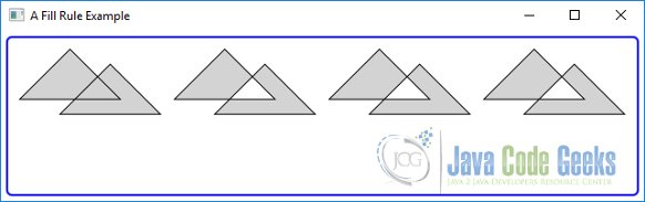
The following image shows paths using different fill rules:
4. Combining Shapes
4.1 The Code
FxComplexShapeExample4.java
import javafx.application.Application;
import javafx.scene.Scene;
import javafx.scene.layout.HBox;
import javafx.scene.paint.Color;
import javafx.scene.shape.Circle;
import javafx.scene.shape.Shape;
import javafx.stage.Stage;

public class FxComplexShapeExample4 extends Application
{
	public static void main(String[] args)
	{
		Application.launch(args);
	}

	@Override
	public void start(final Stage stage)
	{
		// Create the Circles
		Circle circle1 = new Circle (0, 0, 20);
		Circle circle2 = new Circle (15, 0, 20);

		// Create the Shapes
		Shape union = Shape.union(circle1, circle2);
		union.setStroke(Color.BLACK);
		union.setFill(Color.LIGHTGRAY);

		Shape intersection = Shape.intersect(circle1, circle2);
		intersection.setStroke(Color.BLACK);
		intersection.setFill(Color.LIGHTGRAY);

		Shape subtraction = Shape.subtract(circle1, circle2);
		subtraction.setStroke(Color.BLACK);
		subtraction.setFill(Color.LIGHTGRAY);

		// Create the HBox
		HBox root = new HBox(union, intersection, subtraction);
		root.setSpacing(20);

		// Set the Style of the HBox
		root.setStyle("-fx-padding: 10;" +
			"-fx-border-style: solid inside;" +
			"-fx-border-width: 2;" +
			"-fx-border-insets: 5;" +
			"-fx-border-radius: 5;" +
			"-fx-border-color: blue;");

		// Create the Scene
		Scene scene = new Scene(root);
		// Add the Scene to the Stage
		stage.setScene(scene);
		// Set the Title of the Stage
		stage.setTitle("A Combining Path Example");
		// Display the Stage
		stage.show();
	}
}
The Shape class provides three static methods that let you perform union, intersection and subtraction of shapes.
- union(Shape shape1, Shape shape2)
- intersect(Shape shape1, Shape shape2)
- subtract(Shape shape1, Shape shape2)
The methods return a new Shape instance. They operate on the areas of the input shapes. If a shape does not have a fill and a stroke, its area is zero. The new shape has a stroke and a fill.
The union() method combines the areas of two shapes. The intersect() method uses the common areas between the shapes to create the new shape. The subtract() method creates a new shape by subtracting the specified second shape from the first shape.
The following code snippet shows an example of an intersection:
Shape intersection = Shape.intersect(circle1, circle2);
intersection.setStroke(Color.BLACK);
intersection.setFill(Color.LIGHTGRAY);
4.2 The GUI
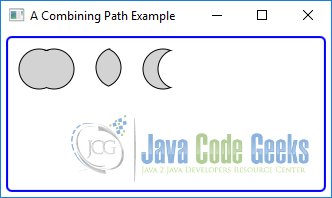
The above program combines two circles using the union, intersection, and subtraction
operations. The following image shows the result:
5. Understanding the Stroke of a Shape
5.1 The Code
FxComplexShapeExample5.java
import javafx.application.Application;
import javafx.geometry.Pos;
import javafx.scene.Scene;
import javafx.scene.layout.HBox;
import javafx.scene.paint.Color;
import javafx.scene.shape.Rectangle;
import javafx.scene.shape.StrokeType;
import javafx.stage.Stage;

public class FxComplexShapeExample5 extends Application
{
	public static void main(String[] args)
	{
		Application.launch(args);
	}

	@Override
	public void start(final Stage stage)
	{
		// Create the Rectangles
		Rectangle rectangle1 = new Rectangle(50, 50);
		rectangle1.setFill(Color.LIGHTGRAY);

		Rectangle rectangle2 = new Rectangle(50, 50);
		rectangle2.setFill(Color.LIGHTGRAY);
		rectangle2.setStroke(Color.BLACK);
		rectangle2.setStrokeWidth(4);
		rectangle2.setStrokeType(StrokeType.INSIDE);

		Rectangle rectangle3 = new Rectangle(50, 50);
		rectangle3.setFill(Color.LIGHTGRAY);
		rectangle3.setStroke(Color.BLACK);
		rectangle3.setStrokeWidth(4);

		Rectangle rectangle4 = new Rectangle(50, 50);
		rectangle4.setFill(Color.LIGHTGRAY);
		rectangle4.setStroke(Color.BLACK);
		rectangle4.setStrokeWidth(4);
		rectangle4.setStrokeType(StrokeType.OUTSIDE);

		// Create the HBox
		HBox root = new HBox(rectangle1, rectangle2, rectangle3, rectangle4);
		root.setAlignment(Pos.CENTER);
		root.setSpacing(10);

		// Set the Style of the HBox
		root.setStyle("-fx-padding: 10;" +
			"-fx-border-style: solid inside;" +
			"-fx-border-width: 2;" +
			"-fx-border-insets: 5;" +
			"-fx-border-radius: 5;" +
			"-fx-border-color: blue;");

		// Create the Scene
		Scene scene = new Scene(root);
		// Add the Scene to the Stage
		stage.setScene(scene);
		// Set the Title of the Stage
		stage.setTitle("A Stroke Type Example");
		// Display the Stage
		stage.show();
	}
}
Stroking is the process of painting the outline of a shape. Sometimes, the outline of a shape is also known as stroke. The Shape class contains several properties to define the appearance of the stroke of a shape.
- stroke
- strokeWidth
- strokeType
- strokeLineCap
- strokeLineJoin
- strokeMiterLimit
- strokeDashOffset
The stroke property specifies the color of the stroke. The default stroke is set to null for all shapes except Line, Path and Polyline, which have Color.BLACK as their default stroke.
The strokeWidth property specifies the width of the stroke. It is 1.0px by default. The stroke is painted along the boundary of a shape.
The strokeType property specifies the distribution of the width of the stroke on the boundary. Its value is one of the three constants, CENTERED, INSIDE, and OUTSIDE, the StrokeType enum. The default value is CENTERED. The CENTERED stroke type draws a half of the stroke width outside and half inside the boundary. The INSIDE stroke type draws the stroke inside the boundary. The OUTSIDE stroke draws the stroke outside the boundary. The stroke width of a shape is included in its layout bounds.
The strokeLineCap property specifies the ending decoration of a stroke for unclosed subpaths and dash segments. Its value is one of the constants of the StrokeLineCap enum: BUTT, SQUARE, and ROUND. The default is BUTT. The BUTT line cap adds no decoration to the end of a subpath; the stroke starts and ends exactly at the starting and ending points. The SQUARE line cap extends the end by half the stroke width. The ROUND line cap adds a round cap to the end. The round cap uses a radius equal to half the stroke width.
The strokeLineJoin property specifies how two successive path elements of a subpath are joined. Its value is one of the constants of the StrokeLineJoin enum: BEVEL, MITER, and ROUND. The default is MITER. The BEVEL line join connects the outer corners of path elements by a straight line. The MITER line join extends the outer edges of two path elements until they meet. The ROUND line join connects two path elements by rounding their corners by half the stroke width.
If the path elements meet at a smaller angle, the length of the join may become very big. You can limit the length of the join using the strokeMiterLimit property. It specifies the ratio of the miter length and the stroke width. The miter length is the distance between the most inside point and the most outside point of the join. If the two path elements cannot meet by extending their outer edges within this limit, a BEVEL join is used instead. The default value is 10.0. That is, by default, the miter length may be up to ten times the stroke width.
By default, the stroke draws a solid outline. You can also have a dashed outline. You need to provide a dashing pattern and a dash offset. The dashing pattern is an array of double that is stored in an ObservableList<Double>. You can get the reference of the list using the getStrokeDashArray() method of the Shape class. The elements of the list specify a pattern of dashes and gaps. The first element is the dash length, the second gap, the third dash length, the fourth gap, and so on. The dashing pattern is repeated to draw the outline. The strokeDashOffset property specifies the offset in the dashing pattern where the stroke begins.
The following code snippet creates a lightgray Rectangle with a black Stroke and a strokeWidth of 4px.
Rectangle rectangle3 = new Rectangle(50, 50);
rectangle3.setFill(Color.LIGHTGRAY);
rectangle3.setStroke(Color.BLACK);
rectangle3.setStrokeWidth(4);
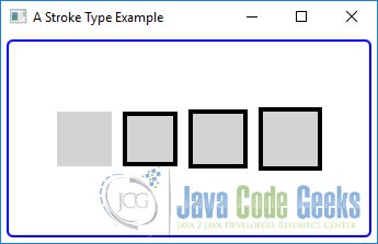
5.2 The GUI
The above program creates four rectangles as shown in the following image. All rectangles have the same width and height.
The first rectangle, counting from the left, has no stroke and it has layout bounds of 50px X 50px. The second rectangle uses a stroke of width 4px and an INSIDE stroke type. The third rectangle uses a stroke width 4px and a CENTERED stroke type, which is the default. The fourth rectangle uses a 4px stroke width and an OUTSIDE stroke type.
6. Download
This was an example of javafx.scene.shape
You can download the full source code of this example here: JavaFxComplexShapeExample.zip