This is a JavaFX Transformation Example. A transformation is a mapping of points in a coordinate space to themselves preserving distances and directions between them. Several types of transformations can be applied to points in a coordinate space. JavaFX supports the following types of transformation:
- Translation
- Rotation
- Shear
- Scale
An instance of the abstract Transform class represents a transformation in JavaFX. The Transform class contains common methods and properties used by all types of transformations on nodes. It contains factory methods to create specific types of transformations.
The following table shows an overview of the whole article:
Table Of Contents
The following examples use Java SE 8 and JavaFX 2.2.
1. The Translation Transformation
1.1 The Code
FxTransformationExample1.java
import javafx.application.Application;
import javafx.scene.Scene;
import javafx.scene.layout.Pane;
import javafx.scene.paint.Color;
import javafx.scene.shape.Rectangle;
import javafx.scene.transform.Translate;
import javafx.stage.Stage;

public class FxTransformationExample1 extends Application
{
	public static void main(String[] args)
	{
		Application.launch(args);
	}

	@Override
	public void start(Stage stage)
	{
		// Create the Rectangles
		Rectangle rectangle1 = new Rectangle(100, 50, Color.LIGHTGRAY);
		rectangle1.setStroke(Color.BLACK);
		Rectangle rectangle2 = new Rectangle(100, 100, Color.YELLOW);
		rectangle2.setStroke(Color.BLACK);
		Rectangle rectangle3 = new Rectangle(180, 100, Color.STEELBLUE);
		rectangle3.setStroke(Color.BLACK);

		// Apply a Translation on Rectangle1 using the transforms sequence
		Translate translate1 = new Translate(50, 40);
		rectangle1.getTransforms().addAll(translate1);

		// Apply a Translation on Rectangle2 using the transforms sequence
		Translate translate2 = new Translate(100, 80);
		rectangle2.getTransforms().addAll(translate2);

		// Apply a Translation on Rectangle3 using the translateX and translateY proeprties
		rectangle3.setTranslateX(180);
		rectangle3.setTranslateY(70);

		// Create the Pane
		Pane root = new Pane(rectangle1, rectangle2, rectangle3);
		// Set the size of the Pane
		root.setPrefSize(400, 300);
		// Set the Style-properties of the Pane
		root.setStyle("-fx-padding: 10;" +
				"-fx-border-style: solid inside;" +
				"-fx-border-width: 2;" +
				"-fx-border-insets: 5;" +
				"-fx-border-radius: 5;" +
				"-fx-border-color: blue;");

		// Create the Scene
		Scene scene = new Scene(root);
		// Add the Scene to the Stage
		stage.setScene(scene);
		// Set the title of the Stage
		stage.setTitle("A Translation Transformation Example");
		// Display the Stage
		stage.show();
	}
}
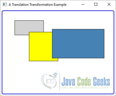
A translation moves every point of a Node by a fixed distance in a specified direction relative to its parent coordinate system. It is achieved by shifting the origin of the local coordinate system of the Node to a new location.
Computing the new locations of points is easy. You only have to add a triplet of numbers to the coordinates of each point in a 3D space. In a 2D space, add a pair of numbers to the coordinates of each point.
Suppose you want to apply translation to a 3D coordinate space by (tx, ty, tz). If a point had coordinates (x, y, z) before the translation, after the translation its coordinates would be (x + tx, y + ty, z + tz).
An instance of the Translate class represents a translation. It contains three properties.
- x
- y
- z
The properties specify the x, y, and z coordinates of the new origin of the local coordinate system of the node after translation. The default values for the properties are 0.0.
The Translate class provides three constructors.
- Translate()
- Translate(double x, double y)
- Translate(double x, double y, double z)
The no-args constructor creates a Translate object with the default values for the x, y, and z properties, which, in essence, represents no Translation. The other two constructors let you specify the Translation distance along the three axes.
The following code snippet shows the usage of the constructor:
// Apply a Translation on Rectangle1 using the transforms sequence
Translate translate1 = new Translate(50, 40);
A transformation to a Group is applied to all the nodes in the Group.
1.2 The GUI
The above program creates three rectangles. By default, they are placed at (0, 0). It applies a translation to all rectangles. The following Figure shows the rectangles after the translation.
2. The Rotation Transformation
2.1 The Code
FxTransformationExample2.java
import javafx.application.Application;
import javafx.scene.Scene;
import javafx.scene.layout.Pane;
import javafx.scene.paint.Color;
import javafx.scene.shape.Rectangle;
import javafx.scene.transform.Rotate;
import javafx.scene.transform.Translate;
import javafx.stage.Stage;

public class FxTransformationExample2 extends Application
{
	public static void main(String[] args)
	{
		Application.launch(args);
	}

	@Override
	public void start(Stage stage)
	{
		// Create the Rectangles
		Rectangle rectangle1 = new Rectangle(150, 100, Color.LIGHTGRAY);
		rectangle1.setStroke(Color.BLACK);
		Rectangle rectangle2 = new Rectangle(150, 100, Color.LIGHTGRAY);
		rectangle2.setStroke(Color.BLACK);

		// Create a Translation
		Translate translate = new Translate(150, 30);

		// Apply a Translation on Rectangle1 using the transforms sequence
		rectangle1.getTransforms().addAll(translate);

		// Apply a Translation on Rectangle2 using the transforms sequence
		rectangle2.getTransforms().addAll(translate);
		rectangle2.setOpacity(0.5);

		// Apply a Rotation on Rectangle2
		Rotate rotate = new Rotate(60, 0, 0);
		rectangle2.getTransforms().addAll(rotate);

		// Create the Pane
		Pane root = new Pane(rectangle1, rectangle2);
		// Set the size of the Pane
		root.setPrefSize(400, 300);
		// Set the Style-properties of the Pane
		root.setStyle("-fx-padding: 10;" +
				"-fx-border-style: solid inside;" +
				"-fx-border-width: 2;" +
				"-fx-border-insets: 5;" +
				"-fx-border-radius: 5;" +
				"-fx-border-color: blue;");

		// Create the Scene
		Scene scene = new Scene(root);
		// Add the Scene to the Stage
		stage.setScene(scene);
		// Set the Title of the Stage
		stage.setTitle("A Rotation Transformation Example");
		// Display the Stage
		stage.show();
	}
}
In a rotation transformation, the axes are rotated around a pivot point in the coordinate space and the coordinates of points are mapped to the new axes.
An instance of the Rotate class represents a rotation transformation. It contains five properties to describe the rotation:
- angle
- axis
- pivotX
- pivotY
- pivotZ
The angle property specifies the angle of rotation in degrees. The default is 0.0 degrees. A positive value for the angle is measured clockwise.
The axis property specifies the axis of rotation at the pivot point. Its value can be one of the constants, X_AXIS, Y_AXIS, and Z_AXIS, defined in the Rotate class. The default axis of rotation is Rotate.Z_AXIS.
The pivotX, pivotY, and pivotZ properties are the x, y, and z coordinates of the pivot point. The default values for the properties are 0.0.
The Rotate class contains several constructors:
- Rotate()
- Rotate(double angle)
- Rotate(double angle, double pivotX, double pivotY)
- Rotate(double angle, double pivotX, double pivotY, double pivotZ)
- Rotate(double angle, double pivotX, double pivotY, double pivotZ, Point3D axis)
- Rotate(double angle, Point3D axis)
The no-args constructor creates an identity rotation, which does not have any effect on the transformed Node. The other constructors let you specify the details.
The following code snippet shows an example of the constructor:
// Apply a Rotation on Rectangle2
Rotate rotate = new Rotate(60, 0, 0);
2.2 The GUI
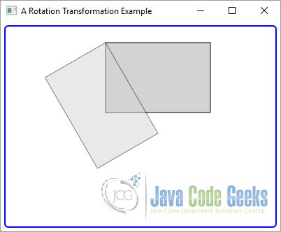
The above program creates two rectangles and places them at the same location. The opacity of the second Rectangle is set to 0.5, so we can see through it. The coordinate system of the second Rectangle is rotated by 60 degrees in the clockwise direction using the origin as the pivot point.
The following Image shows the rotated rectangle.
3. The Scale Transformation
3.1 The Code
FxTransformationExample3.java
import javafx.application.Application;
import javafx.scene.Scene;
import javafx.scene.layout.Pane;
import javafx.scene.paint.Color;
import javafx.scene.shape.Rectangle;
import javafx.scene.transform.Translate;
import javafx.stage.Stage;

public class FxTransformationExample3 extends Application
{
	public static void main(String[] args)
	{
		Application.launch(args);
	}

	@Override
	public void start(Stage stage)
	{
		// Create the Rectangles
		Rectangle rectangle1 = new Rectangle(200, 150, Color.LIGHTGRAY);
		rectangle1.setStroke(Color.BLACK);
		rectangle1.setOpacity(0.5);
		Rectangle rectangle2 = new Rectangle(200, 150, Color.GREEN);
		rectangle2.setStroke(Color.BLACK);

		// Create the Translations
		Translate translate1 = new Translate(200, 100);
		Translate translate2 = new Translate(100, 50);

		// Apply a Translation on Rectangle1
		rectangle1.getTransforms().addAll(translate2);

		// Apply a Translation on Rectangle2
		rectangle2.getTransforms().addAll(translate1);

		// Apply a Scale on Rectangle
		rectangle2.setScaleX(0.5);
		rectangle2.setScaleY(0.5);

		// Create the Pane
		Pane root = new Pane(rectangle1, rectangle2);
		// Set the size of the Pane
		root.setPrefSize(400, 300);
		// Set the Style-properties of the Pane
		root.setStyle("-fx-padding: 10;" +
				"-fx-border-style: solid inside;" +
				"-fx-border-width: 2;" +
				"-fx-border-insets: 5;" +
				"-fx-border-radius: 5;" +
				"-fx-border-color: blue;");

		// Create the Scene
		Scene scene = new Scene(root);
		// Add the Scene to the Stage
		stage.setScene(scene);
		// Set the Title of the Stage
		stage.setTitle("A Scale Transformation Example");
		// Display the Stage
		stage.show();
	}
}
A scale transformation scales the unit of measurement along axes of a coordinate system by a scale factor. This causes the dimensions of a Node to change (stretch or shrink) by the specified scale factors along axes. The dimension along an axis is multiplied by the scale factor along that axis. The transformation is applied at a pivot point whose coordinates remain the same after the transformation.
An instance of the Scale class represents a Scale transformation. It contains the following six properties to describe the transformation:
- x
- y
- z
- pivotX
- pivotY
- pivotZ
The x, y, and z properties specify the scale factors long the x-axis, y-axis, and z-axis. They are 1.0 by default.
The pivotX, pivotY, and pivotZ properties are the x, y, and z coordinates of the pivot point. The default values for the properties are 0.0.
The Scale class contains several constructors.
- Scale()
- Scale(double x, double y)
- Scale(double x, double y, double z)
- Scale(double x, double y, double pivotX, double pivotY)
- Scale(double x, double y, double z, double pivotX, double pivotY, double pivotZ)
The no-args constructor creates an identity Scale transformation, which does not have any effect on the transformed Node. The other constructors let you specify the scale factors and the pivot point.
The following snippet of code applies a Scale on a Rectangle by usage of the Setters.
// Apply a Scale on Rectangle
rectangle2.setScaleX(0.5);
rectangle2.setScaleY(0.5);
You can use an object of the Scale class or the scaleX, scaleY, and scaleZ properties of the Node class to apply a Scale transformation. By default, the pivot point used by the Scale class is at (0, 0, 0). The properties of the Node class use the center of the node as the pivot point.
3.2 The GUI
The above Java Class creates two rectangles. Both are placed at the same location. One of them is scaled and the other not. The opacity of the not scaled Rectangle is set to 0.5, so we can see through it.
The following GUI shows the rectangles. The scaled Rectangle is smaller. The coordinate system of the second Rectangle is scaled by 0.5 along the x-axis and 0.5 along the y-axis. The scaleX and scaleY properties are used to apply the transformation, which uses the center of the rectangles as the pivot point making the rectangles shrunk, but keeping it at the same location.


4. The Shear Transformation
4.1 The Code
FxTransformationExample4.java
import javafx.application.Application;
import javafx.scene.Scene;
import javafx.scene.layout.Pane;
import javafx.scene.paint.Color;
import javafx.scene.shape.Rectangle;
import javafx.scene.transform.Shear;
import javafx.scene.transform.Translate;
import javafx.stage.Stage;

public class FxTransformationExample4 extends Application
{
	public static void main(String[] args)
	{
		Application.launch(args);
	}

	@Override
	public void start(Stage stage)
	{
		// Create the Rectangles
		Rectangle rectangle1 = new Rectangle(200, 100, Color.LIGHTGRAY);
		rectangle1.setStroke(Color.BLACK);
		Rectangle rectangle2 = new Rectangle(200, 100, Color.LIGHTGREEN);
		rectangle2.setStroke(Color.BLACK);

		// Create a Translation
		Translate translate = new Translate(100, 30);

		// Apply a Translation on Rectangle1 using the transforms sequence
		rectangle1.getTransforms().addAll(translate);

		// Apply a Translation on Rectangle2 using the transforms sequence
		rectangle2.getTransforms().addAll(translate);
		rectangle2.setOpacity(0.5);

		// Apply a Shear on Rectangle2
		Shear shear = new Shear(0.5, 0.5);
		rectangle2.getTransforms().addAll(shear);

		// Create the Pane
		Pane root = new Pane(rectangle1, rectangle2);
		// Set the size of the Pane
		root.setPrefSize(400, 300);
		// Set the Style-properties of the Pane
		root.setStyle("-fx-padding: 10;" +
				"-fx-border-style: solid inside;" +
				"-fx-border-width: 2;" +
				"-fx-border-insets: 5;" +
				"-fx-border-radius: 5;" +
				"-fx-border-color: blue;");

		// Create the Scene
		Scene scene = new Scene(root);
		// Add the Scene to the Stage
		stage.setScene(scene);
		// Set the Title of the Stage
		stage.setTitle("A Shear Transformation Example");
		// Display the Stage
		stage.show();
	}
}
A shear transformation rotates axes of the local coordinate system of the Node around a pivot point, so the axes are no longer perpendicular. A rectangular Node becomes a parallelogram after the transformation.
An instance of the Shear class represents a shear transformation. It contains four properties to describe the transformation.
- x
- y
- pivotX
- pivotY
The x property specifies a multiplier by which the coordinates of points are shifted along the positive x-axis by a factor of the y coordinate of the point. The default is 0.0.
The y property specifies a multiplier by which the coordinates of points are shifted along the positive y-axis by a factor of the x coordinate of the point. The default is 0.0.
The pivotX, and pivotY properties are the x and y coordinates of the pivot point about which the shear occurs. The default values for them are 0.0. The pivot point is not shifted by the Shear.
By default, the pivot point is the origin of the untransformed coordinate system.
Suppose you have a point (x1, y1) inside a Node, and by the Shear transformation, the point is shifted to (x2, y2). You can use the following formula to compute (x2, y2):
x2 = pivotX + (x1 - pivotX) + x * (y1 - pivotY)
y2 = pivotY + (y1 - pivotY) + y * (x1 - pivotX)
All coordinates (x1, y1, x2, and y2) in the previous formula are in the untransformed local coordinate system of the Node. Notice that if (x1, y1) is the pivot point, the foregoing formula computes the shifted point (x2, y2), which is the same as (x1, y1). That is, the pivot point is not shifted.
The Shear class contains several constructors.
- Shear()
- Shear(double x, double y)
- Shear(double x, double y, double pivotX, double pivotY)
The no-args constructor creates an identity Shear transformation, which does not have any effect on the transformed Node. The other constructors let you specify the shear multipliers and the pivot point.
The following code snippet applies a Shear on the second Rectangle.
// Apply a Shear on Rectangle2
Shear shear = new Shear(0.5, 0.5);
4.2 The GUI
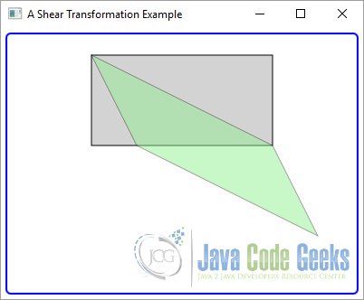
The above program applies a Shear to a Rectangle as shown in the following GUI. The original Rectangle is also shown. A multiplier of 0.5 is used along both axes. Note that the pivot point is (100, 30).
5. Applying Multiple Transformations
5.1 The Code
FxTransformationExample5.java
import javafx.application.Application;
import javafx.scene.Scene;
import javafx.scene.layout.Pane;
import javafx.scene.paint.Color;
import javafx.scene.shape.Rectangle;
import javafx.scene.transform.Rotate;
import javafx.scene.transform.Scale;
import javafx.scene.transform.Translate;
import javafx.stage.Stage;

public class FxTransformationExample5 extends Application
{
	public static void main(String[] args)
	{
		Application.launch(args);
	}

	@Override
	public void start(Stage stage)
	{
		// Create the Rectangles
		Rectangle rectangle1 = new Rectangle(150, 100, Color.LIGHTGRAY);
		rectangle1.setStroke(Color.BLACK);
		Rectangle rectangle2 = new Rectangle(150, 100, Color.LIGHTBLUE);
		rectangle2.setStroke(Color.BLACK);
		Rectangle rectangle3 = new Rectangle(150, 100, Color.LIGHTCYAN);
		rectangle3.setStroke(Color.BLACK);

		// Create a Translation
		Translate translate = new Translate(100, 40);

		// Apply a Translation on Rectangle1 using the transforms sequence
		rectangle1.getTransforms().addAll(translate);

		// Apply a Translation on Rectangle2 using the transforms sequence
		rectangle2.getTransforms().addAll(translate);
		rectangle2.setOpacity(0.5);

		// Apply a Translation on Rectangle3 using the transforms sequence
		rectangle3.getTransforms().addAll(translate);
		rectangle3.setOpacity(0.5);

		//Apply Transformations to Rectangle2
		rectangle2.setTranslateX(100);
		rectangle2.setTranslateY(0);
		rectangle2.setRotate(30);
		rectangle2.setScaleX(1.2);
		rectangle2.setScaleY(1.2);

		// Apply Transformation to Rectangle3
		rectangle3.getTransforms().addAll(new Scale(1.2, 1.2, 50, 25),
				new Rotate(30, 50, 25),new Translate(100, 0));

		// Create the Pane
		Pane root = new Pane();
		// Set the size of the Pane
		root.setPrefSize(400, 300);
		// Add the Children to the Pane
		root.getChildren().addAll(rectangle1, rectangle2, rectangle3);
		// Set the Style-properties of the Pane
		root.setStyle("-fx-padding: 10;" +
				"-fx-border-style: solid inside;" +
				"-fx-border-width: 2;" +
				"-fx-border-insets: 5;" +
				"-fx-border-radius: 5;" +
				"-fx-border-color: blue;");

		// Create the Scene
		Scene scene = new Scene(root);
		// Add the Scene to the Stage
		stage.setScene(scene);
		// Set the Title of the Stage
		stage.setTitle("A Multiple Transformations Example");
		// Display the Stage
		stage.show();
	}
}
You can apply multiple transformations to a Node. As mentioned previously, the transformations in the transforms sequence are applied before the transformation set on the properties of the Node.
When properties of the Node class are used, Translation, Rotation, and Scale are applied in sequence. When the transforms sequence is used, transformations are applied in the order they are stored in the sequence.
The following code snippet creates three rectangles and positions them at the same location. It applies multiple transformations to the second and third rectangles in different order.
// Create a Translation
Translate translate = new Translate(100, 40);

// Apply a Translation on Rectangle1 using the transforms sequence
rectangle1.getTransforms().addAll(translate);

// Apply a Translation on Rectangle2 using the transforms sequence
rectangle2.getTransforms().addAll(translate);
rectangle2.setOpacity(0.5);

// Apply a Translation on Rectangle3 using the transforms sequence
rectangle3.getTransforms().addAll(translate);
rectangle3.setOpacity(0.5);

//Apply Transformations to Rectangle2
rectangle2.setTranslateX(100);
rectangle2.setTranslateY(0);
rectangle2.setRotate(30);
rectangle2.setScaleX(1.2);
rectangle2.setScaleY(1.2);
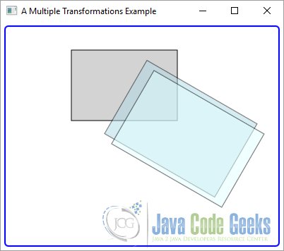
The first Rectangle is shown at its original position, as we did not apply any transformation to it. Notice that two rectangles ended up at different locations. If you change the order of the transformation for the third Rectangle as shown next, both rectangles will overlap.
// Apply Transformation to Rectangle3
rectangle3.getTransforms().addAll(new Scale(1.2, 1.2, 50, 25),
		new Rotate(30, 50, 25),new Translate(100, 0));
5.2 The GUI
The following GUI shows the result of the above program.
6. Download Java Source Code
This was an example of javafx.scene.transform
You can download the full source code of this example here: JavaFxTransformationExample.zip